|
Voltage Tracker for Oscilloscope My Digital Oscilloscope has a timebase of maximum 50 seconds per DIV and a 12 DIV screen, which gives a mere 10 minutes for following a voltage. Much too fast to track charging or discharging batteries or other slow changing events. An Arduino Mega 2560 with the here introduced shield expands the oscilloscopes tracking time up to 12 hours, or more. As a deposit all necessary settings are displayed on the oscilloscope screen. Of course the shield works on good old analog oscilloscopes as well. |
|
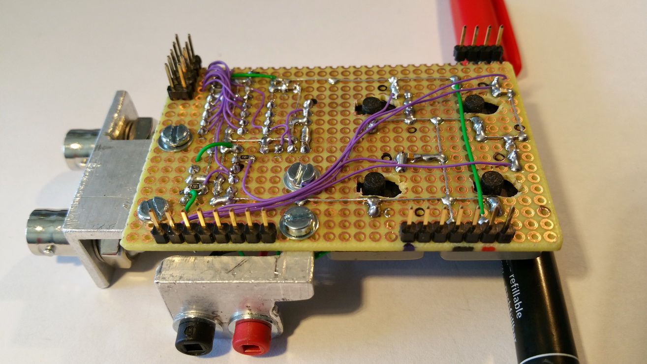
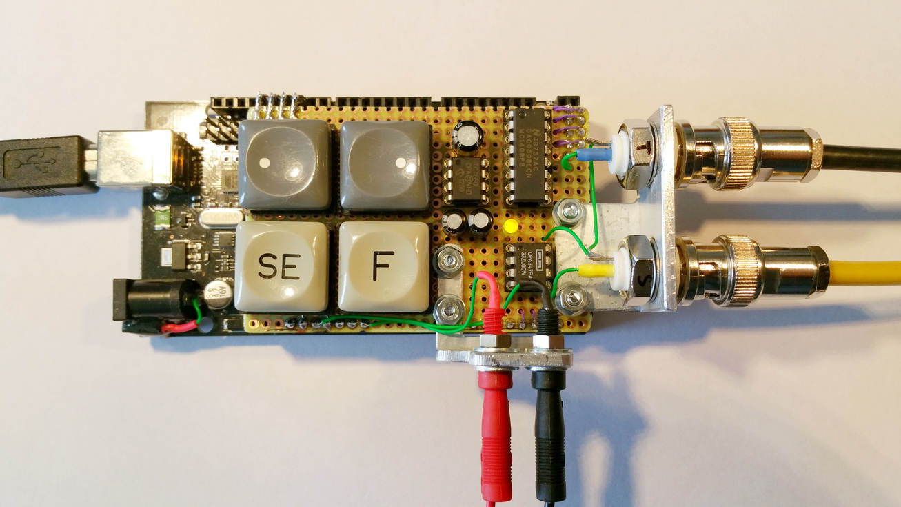
The Shield consists of four push buttons, a digital to analog converter, a negative supply, a rail to rail operational amplifier, two input and output jacks, a control LED and some pole connectors, resistances and capacitors. Arduino and shield can be powered by USB or a 7.5 to 12 V mains adapter. The red and black plugs on the front lead to the test voltage. The BNC plugs on the right are connected to the oscilloscope. The black wire to the trigger source, the yellow one to an arbitrary channel. The upper buttons decrease and increase settings. SE button starts settings and switches through them. A short press on F starts or stops tracking, a long press on F deletes the current tracking curve. The LED stays dark in setting mode, blinks while tracking and will light constant when tracking is stopped. The oscilloscope does not have to run during tracking and can be switched on and off at any time, without loss of results. For proper presentation the oscilloscope should be set 10 ms horizontal and 2 V vertical. All settings are stored persistently in Arduinos EEPROM. |
|
|
time Setting Steps Time/DIV Duration (@ 12 DIV Screen) |
|

|
level Setting Steps Offset (@ Vcc 5 V) The zero line would be set to 3.0 V in this example. In cooperation with y-scale setting, be sure to make meaningful adjustments. Be careful, the all over input range must not exceed 5.0 V, higher voltages might damage the Ardino. |
|
|
roll Setting Steps Screen Roll |
|
|
y-Scale Setting Steps Osci Y Range Level Max A level setting of 3.0 V with y-scale 0 (range 1.25 V), means the voltage will be tracked between 3.0 V and 4.25 V, best suited for tracking LithIo (dis)charging. In cooperation with level setting, be sure to make meaningful adjustments. |
|
|
number of DIVs Setting Steps Osci Y Range Level Max |
|

|
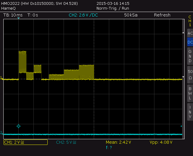
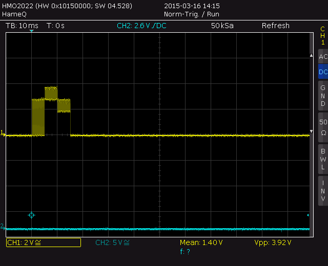
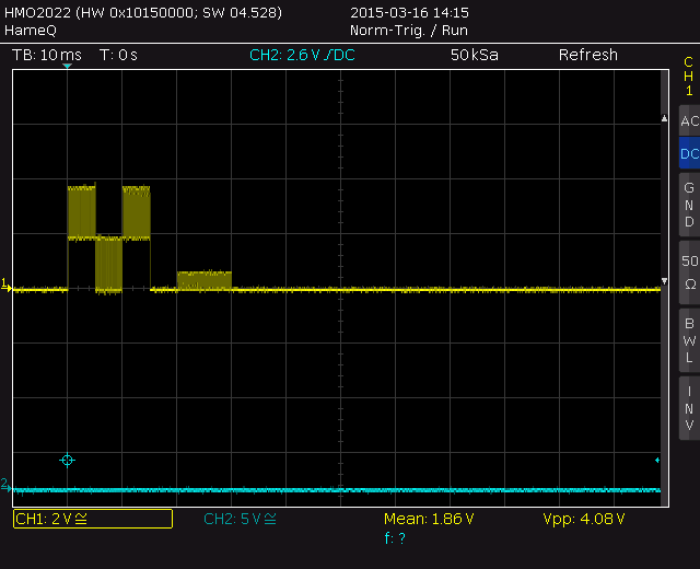
Example Discharge of a LithIo Battery, stopping the discharge at about 3.3 V. After that the recovery of the cell to a level lightly lower than before discharge. Shield time setting 1 min / DIV -> total screen 12 min. Shield zero level 3.0 V and y-scale 0 (1/4), osci y at 1V/DIV makes 0.25V/DIV for this protocol. |
|

|
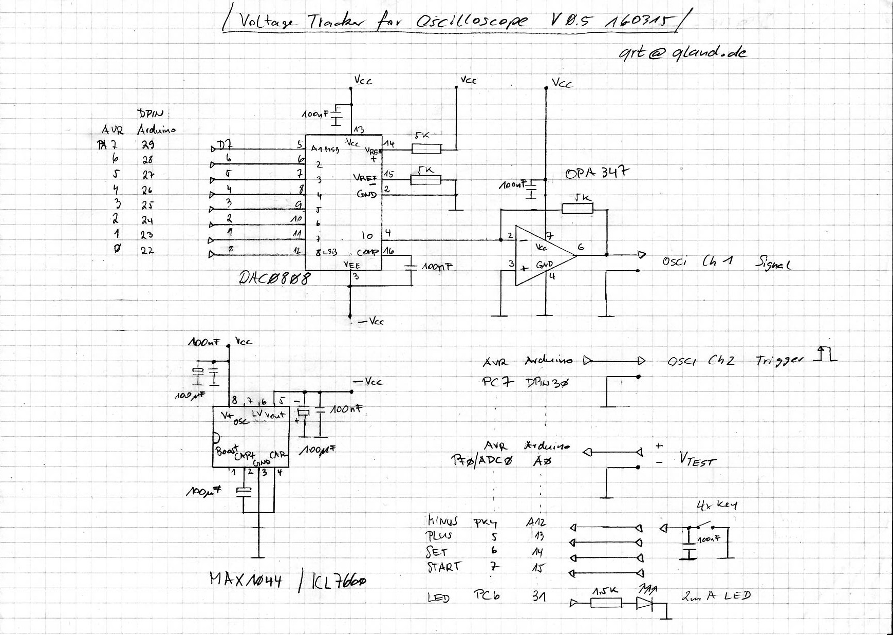
Schematic |
|
|
|
|